High availability reference architecture
High Availability reference architecture and connections
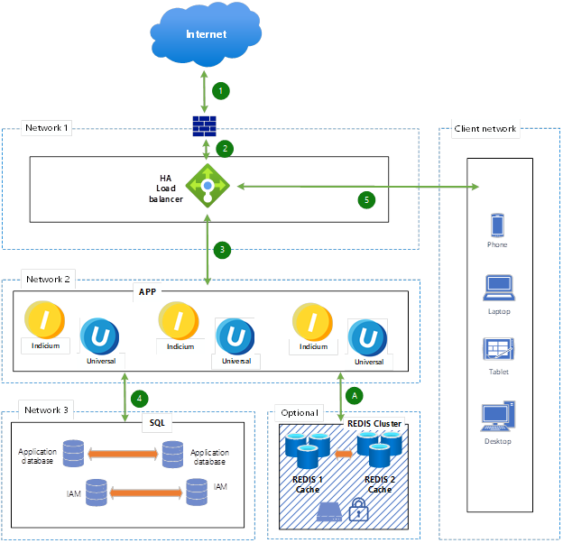
The diagram below represents a high availability architecture with multiple networks, load balancing, caching, and database redundancy. The numbered steps indicate the traffic flow in the system.
See also:
 High availability reference architecture
Connections:
- Incoming request from the Internet
A client (phone, laptop, tablet, desktop) sends a request over the internet. - Traffic goes through the firewall
The request is inspected by a firewall for security before it reaches the load balancer. - Load balancer distributes traffic to app servers
The High Availability (HA) Load Balancer determines the best available application server and forwards the request. - App servers interact with the database
The application servers process the request and, if needed, query the HA SQL database for data. - Response is sent back to the client
The processed response is sent back through the load balancer, then through the firewall, and finally reaches the client device.
A. Optional: Cache (Redis) usage
If caching is enabled, the application servers can retrieve frequently used data from Redis caches (instead of querying the database) to improve performance.